![]()
![]()
![]()
 Piping Common
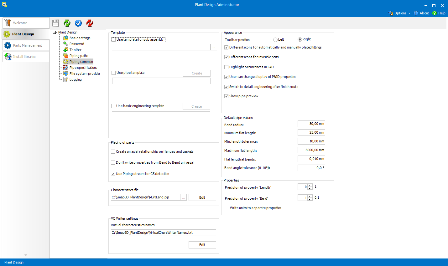
In the Piping Common tab, you can make various settings which apply to working with Piping.
When Use template for subassembly is set and a template selected, it can be used for automatic creation of subassemblies in Smap3D Piping and P&ID To-Do List.
If the option is not active, system internal CAD templates are used.
If there are some specific file properties which should be written to the pipes when
these are generated, they can be taken from the template Part file. 
Use basic engineering template
Use basic engineering template provides more information to the basic engineering pipes.
This template can now be set in the Plant Design Administrator > Piping common in the Template section.
Create makes a copy of the Smap3D internal basic engineering pipe template and saves it as SOLIDWORKS template file with the name SWBasicTubeTemplate.prtdot in the Smap3D configuration folder. Template can be extended with user-specific properties from material information (SOLIDWORKS material library) as required.
For the update of the physical properties in the generated basic engineering pipes to work correctly, the template file must contain at least the user-defined file properties Material and MaterialLib with correct and appropriate values.
Changes to the given sketches, features and equations in the template must NOT be made, otherwise the automatic pipe generation with Piping will not work anymore!
 Changes
to the given sketches, features and equations in the template must NOT
be made, otherwise the automatic pipe generation with Piping will not
work anymore!
Changes
to the given sketches, features and equations in the template must NOT
be made, otherwise the automatic pipe generation with Piping will not
work anymore!
Define file properties and material definitions in the set template, that should be written to the individual pipe files when generating the basic engineering pipes in the set template.
Create an axial relationship on flanges and gaskets affects creating of axial relationships for automatically placed flanges and gaskets.
Axial relationships can potentially
cause the assembly to be overdefined, or other mates to be disrupted.
 This setting is also available in Smap3D
Piping menu Tools
- Options.
This setting is also available in Smap3D
Piping menu Tools
- Options.
When Don't write properties from Bend to Bend universal option is set, the Bend universal fittings used within the generate pipelines do not take over properties from Bend 90 or Bend 180 respectively.
Use Piping stream for CS detection is checked by default. It should be unselected only when expecting problems with Coordinate Systems detection.
The option turns off reading of extended information for CS of standard parts which were created by Plant Design tools.
For some functions Smap3D Piping gets values of various parameters from standard part characteristics.
The Characteristics file (*.pip) is used for correctly interpreting the characteristic names and their geometrical values in standard parts.
There is a pre-defined characteristics file called MultiLang.pip in the Smap3D program folder (default path is C:\Program Files (x86)\Cad-Partner\Smap3D Plant Design [Version]).
This file is prepared for the Smap3D library plant design components.
In the left column there are system characteristics. For the selected system characteristic, you can specify the corresponding characteristic names (could be in multiple languages) which are used in your standard parts.
When using File system provider, the parameter values must be stored in specific custom properties (instead of characteristics).
The names of those properties are based on the system characteristics.
These must begin with the PD_ prefix followed by the system characteristic name where all spaces are replaced by an underscore (e.g. PD_Outer_diameter, PD_Wall_thickness, etc.).
The system characteristics are
as follows:
Outer diameter, Wall thickness
These parameters are necessary for generating pipes (when generating
pipes, Piping does not use 3D geometry of the parts specified in the
respective Pipe Specifications
as standard parts). The values of the respective characteristics must
have dimension of length.
For the file system provider, the value of the respective custom property
must contain a unit (e.g. 100 mm, 4", etc.).
Bend radius, Minimum flat length, Maximum flat
length
Setting characteristics for these parameters is optional. The parameters
set within the respective pipe specification
or the default pipe values (see below) have higher priority.
Bend angle
The characteristic that controls angle of the component specified as
Bend
Universal or Elbow Universal. It must be a variable characteristic
that controls the 3D model equation that
specifies the angle.
File System Provider: the value of the respective custom property must
be the name of the equation.
Shape tube length
The characteristic that controls length of the component specified
as Shape Pipe. It must
be a variable characteristic that controls the 3D model equation that
specifies length of the shape
pipe.
For the file system provider, the value of the respective custom property
must be the name of the equation.
Shape components orientation
Specifies orientation of the respective shape component. The characteristic
must be dimensionless with an integer value from 0 to 6 (see Shape
Components for details).
Bolt diameter, Bolt Length, Bolt thread
Specifies parameters of virtual
fasteners that can be set as additional
items for Piping components.
In this section you can set/edit the set of custom virtual characteristics that should be managed by the Virtual Characteristic Writer.
The set is written within the VirtualCharsWriterNames.txt file stored in the Plant Design configuration folder.
Each row within the file represents one custom virtual characteristic name. In other words, the names are separated with the new line separator. See Using Virtual Characteristic Writer for details.
Toolbar position determines if the toolbar should appear on the Left or Right side of the Piping application window, when running as CAD external application.
In the standard application (integrated in CAD as ribbon) this option has no effect/significance.
Different icons for automatically and manually placed fittings and Different icons for invisible parts affect the icons in Piping treeview.
The next checkbox enables to Highlight occurrences in CAD when the cursor is over it in the Piping treeview.
User can
change display of P&ID properties allows/disallows the user
to check individual component and pipeline properties to be displayed
in the properties table of P&ID
To-Do List and also written into a CAD occurrences (as virtual characteristics) when assigned .
Switch to detail engineering after finish route
If the option is checked the detailed engineering will be automatically generated after closing a 3D sketch with a new pipeline path.
Detailed engineering means that the pipeline will be generated with a desired pipe specification.
If checked, a preview pipe will be shown during drawing a new pipeline path in the 3D sketch.
Default pipe values can be set in this group. Bend radius represents the radius of a bend on a generated pipe.
Pipes are generated only on segments which are equal or longer than Minimum Flat Length.
If the Min. Length Tolerance is set, segments shorter than this value are suppressed (therefore pipes are not generated over them).
Maximum Flat Length is the length of the longest straight segment on which a pipe can be generated.
These three settings are also possible to set individually for a pipe specification in the Pipe Specification Editor.
The parameter Flat Length At Bends is used when a pipeline with the checked option Divided is generated (see Generating a pipeline for details).
It defines the cylindric volume which can be added to both sides
of each bent pipe part .
The Bend Angle Tolerance parameter applies only if a Bend/Elbow universal fitting is defined for the respective pipe specification.
If some value is set greater than zero (max. 10,0°), than Bend/Elbow universal fittings are not placed where line segments form a supplementary angle to the set tolerance.
Most of
these default values can be set individually for each pipe specification
in Pipe specification
editor.
These settings allow to set the number of decimal places which the properties Length and Bend should have.
These properties are automatically written when the pipes are generated.
These
settings have influence on values in the Piping message boxes.
For example the minimum length of a pipe is 100 mm
from pipe specification. The length of a pipe in a CAD is 99.9 mm.
If the precision is set to zero decimal places the message box will show
- Wrong length of a pipe: 100 mm. The minimum length must be 100 mm.
When this setting is checked, the custom file properties Length (and Bend) in pipes will contain numbers only, units are stored in separated properties Length_Unit (and Bend_Unit).
In order for settings to be saved,
use Save
settings when Plant
Design tab is opened.