![]()
![]()
![]()
There are several terms that should be understood before starting to work with Smap3D Piping:
Pipeline path is a fundamental part of Smap3D Piping. It is used for creating fitting relationships and as a base for creating pipes.
Segment is a part of a pipeline path lying in between two fittings or more precisely between two coordinate systems.
Pipe is made on a segment by the Piping software and it contains a special custom property Piping with value of True.
Pipe specification is generally a catalog of piping components typically used together to form a pipeline for specific conditions (such as flowing medium, operating conditions, design parameters, etc.). These pipe specifications control the numerous automatic functions of the Smap3D Piping software.
For the detailed information about pipe specifications please refer to the Pipe Specification Editor section of this help.
Standard parts provider is generally something (PDM system, application, plug-in, etc.) that provides Piping with component files. Those files are specified within pipe specifications and thus Piping can compose pipelines of the respective components.
One main standard parts provider is required, and it may be supplemented by other additional providers (see Pipe Specifications settings of Plant Design Administrator for details).
Smap3D Piping supports automatic placing of many component types. The names (keywords) of those component types are defined in the common settings file of Pipe Specification Editor (PipeSpecificationCommon.pssx) which can be managed via Plant Design Administrator (Pipe Specifications) or Pipe Specification Editor.
Pipe defines a part which contains the characteristics Diameter and Wall thickness or some equivalent characteristic defined in the characteristics file (see Piping Common for details).
These characteristics (and not the 3D geometry of the pipe) are used for generating Piping pipes. If the line segments make an angle, the pipe will generate a bend at that point (if there is no bend fitting set for such an angle).
When Divided is checked, a bend is generated at that point.
Bend or Elbow 5, 11, 15, 22, 30, 45, 60, 75, 85, 87, 88, 90, 92, 93 and 95 define parts which are automatically placed where line segments form a supplementary angle to the bend value (e.g. Bend/Elbow 45 is placed on 135° angle). The real bend values for Bend/Elbow 5, 11 and 22 are 5 5/8°, 11 1/4°, 22 1/2°.
Bend or Elbow 180 is not a category of fittings which can be placed automatically. It serves just as a source of file properties (Part name especially) for the pipe bends (angle between 90° and 180°) generated with the Divided checked.
Bend/Elbow universal can be placed automatically to the positions where line segments form a common angle, i.e. no other bend fitting (described above) is placed automatically there.
To this keyword a special component (standard part) should be assigned. Such a standard part should have a variable characteristic (equation) driving an angle between its inputs. The characteristic name should be assigned to Bend angle in the characteristics file (see Piping Common for details) for proper function.
Slope dummy defines a part which is automatically placed on a bend connection with angle of >0° and less than bend tolerance. Slope dummy is placed when there is no Bend defined for the given bend angle.
Tee defines a part which is automatically placed on tee connection with an angle of 90°.
Tee Reduced defines a part which is
automatically placed on a tee connection with an angle of 90° where pipelines
with different diameters are connected. 
Tee 11, 22, 45, 85 and 87 define parts which are automatically placed on tee connections with angles of 11 1/4°, 22 1/2°, 45°, 85° and 87°, respectively.
Tee
11 Reduced, Tee 22 Reduced, Tee 45 Reduced, Tee 85 reduced, Tee 87 reduced
define parts which are automatically placed on tee connections
with angles of 11 1/4°, 22 1/2°, 45°, 85° and 87° where pipelines with
different diameters are connected.
Collar (Olet) also defines a part which is automatically placed on a tee connection with an angle of 90° where pipelines with different diameter are connected. Collar is connected by the end which has End Treatment value of ET=10 ( Butt Weld - Branch) on this tee connection. Reduced tees and collars differ in geometry and its coordinate system definitions.
Branch defines a part which is automatically placed on tee connection with an angle of 90°. Branch is connected by the end which has End Treatment value of 10 ( Butt Weld - Branch) on this tee connection. Branch components usually contain only construction geometry (no real volume geometry) and thus differ from collars/olets.
Concentric Reducer defines a part which can be placed interactively by the user when Place one concentric reducer or Place concentric reducer twice is performed. Since these commands usually serve to change pipe specification (or its parameters) for some part of the pipeline, concentric reducers and various adapters are supposed to be set as concentric reducers. Automatic placement of exc. components and exc. reducers is supported, but the pipeline path is NOT changed eccentrically.
Flange defines a part which is automatically placed on coordinate systems with flanged End Treatment.
A flange (and a gasket if defined) is also placed automatically to any pipeline path end point which has some mate to any other assembly level. If you want to set a different behavior for some specific pipeline path end, an auxiliary part must be used that contains an OUTPUT_POINT coordinate system (and OUTPUT_AXIS) with a different End Treatment (set by means of CSInfo). The origin of such a coordinate system must be placed at the pipeline path end point.
Spool Flange defines a part which is automatically placed to an end of a not connected pipeline path, similarly to end components but coordinate systems must be inside the pipeline path.
Counterflange defines a part which is automatically placed (together with a gasket typically) to a free flange (e.g. manually placed flange, or in case a flanged component is defined as cutoff), or to a component which has set End Treatment value to 1002 (Counter flanged) or 1003 (Counter flanged without gasket) in the CSInfo of the respective OUTPUT_POINT coordinate system.
Gasket
defines a part which is automatically placed with flanges. Gaskets cannot
be placed separately.
Custom Gasket defines a part from active Standard Parts Provider which is automatically placed to a component with End Treatment value of 1005 (Custom Gasket Flanged) or 1006 (Custom Gasket Counter Flanged). Custom gasket can be used together with a normal gasket in one pipe spec for one diameter and different virtual characteristics definitions.
Lap Joint typically fastens the connection of two adjacent fittings or pipes. It could be e.g. union nuts, assemblies of union flanges with fasteners, or other joining components. See more about Lap Joints here.
Clamp defines a part which is automatically placed over a gasket with End Treatment value of 18 (Tri Clamp Coupling). Typically used to connect two tri-clamp connections (e.g. valve and connector/flange).
Cutoff defines a part which is automatically placed only if the Cut off pipes after reaching maximum length and place part automatically is enabled. Such a part is then placed to a pipeline path every time the maximum flat length is reached. The disadvantage of this method is that the pipes generated between the cutoffs are shorter than the maximum flat length parameter. They are shortened by the cutoff length (distance between its OUTPUT_POINT coordinate systems - see below) and eventually by further automatically placed parts (e.g. flange and gasket when a flange is set as a cutoff).
 The Cut
off pipes after reaching maximum length and place part automatically
option can be set separately for each pipe specification in the Pipe Specification
Editor.
The Cut
off pipes after reaching maximum length and place part automatically
option can be set separately for each pipe specification in the Pipe Specification
Editor.
Union defines a set of parts which, assembled together, connect two pipes. Similar to a cutoff, a union is placed automatically only if Cut off pipes after reaching... is set. But compared to a cutoff, the advantage of the union is that the pipe between two automatically placed unions reaches exactly the maximum flat length.
A union can be composed of up to four components which can be set as union sub-items (sub-rows) in the Pipe Specification Editor. The component key names are Flange, Counterflange, Gasket and LapJoint. Typically, the Flange and Counterflange are parts mounted to pipe ends and there is a Gasket between them. For the LapJoint there is a component that holds the entire joint together (e.g. a nut).
Coupling defines a component that is automatically placed to connect a component end with End treatment value of 9 (Socket) and a pipe. It can be also placed between adjacent ends (with socket End Treatment) of two components (see Couplings for details).
End Component represents a part which should be placed automatically to all pipeline free ends. End component serves typically to place blind flanges or caps, but it can also represent a flange, coupling, connector, etc.
Support stands for a component (some kind of support typically) which is intended to be placed along pipelines using Place component pattern.
Grooved Coupling defines a part which is placed automatically to connect other components that have socket End Treatment together or with a pipe in between. One grooved coupling is placed to connect two components. Two grooved couplings are placed one at end of each component and a pipe is generated between them. More information about grooved couplings can be found here.
Threaded Joint Nipple defines a part which is placed automatically on a component/fitting with End Treatment value of 16 (Cone Spigot). Reduced Threaded Joint Nipple is supported as well. More information about hydraulic components can be found here.
Threaded Joint Socket Unit defines a part which is placed automatically on a component/fitting with End Treatment value of 15 (Cone Socket Ends). Threaded Joint Socket Unit can have defined up to 3 components (Component 1, Component 2 and Nut). Reduced Threaded Joint Socket Unit is supported as well. More information about Hydraulic components can be found here.
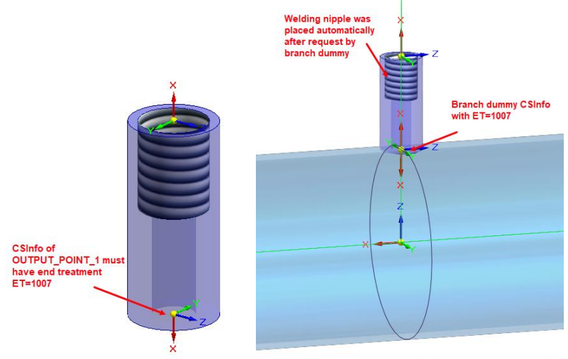
Welding Nipple defines a part which is placed automatically to a component on a pipeline with End Treatment value of 1007, most commonly at branch connection point of an unreinforced branch part with End Treatment value of 10 (Butt Weld - Branch) and 1007 (Welding Nipple). No pipe is generated on a pipeline where Welding Nipple is located.
Shape Pipe defines a part which can be used when no pipes (round) should be placed on a flat line segment.
In contrast to the pipe, for the shape pipe the generating process uses the 3D geometry of the part assigned in the Pipe Specification Editor.
Shape pipe part must contain
a variable characteristic Length or some equivalent characteristic defined
in the characteristics file (see Piping Common for
details).
Limitations:
Shape pipes cannot be bent or divided.
Shape Bend 90 Left, Shape Bend 90 Right, Shape Bend 90 Up and Shape Bend 90 Down define shape parts which are placed automatically on places where line segments form angle of 90°. The fittings differ according to the orientation.
Shape Bend 45 Left, Shape Bend 45 Right, Shape Bend 45 Up and Shape Bend 45 Down define shape parts which are placed automatically on places where line segments form angle of 135°. The fittings differ according to the orientation.
Shape Tee Left, Shape Tee Right, Shape Tee Up and Shape Tee Down define shape parts which can be placed automatically on tee connections with angle of 90°. The fittings differ according to the orientation.
Shape Tee 45 Left, Shape Tee 45 Right, Shape Tee 45 Up and Shape Tee 45 Down define shape parts which can be placed automatically on tee connections with angle of 45° (135°).
Shape
Tee Left Red. and Shape Tee Right
Red. define parts which are placed automatically on tee connections
with angle of 90° where pipelines with different diameters are connected.
Shape Gasket defines a part which is placed automatically between shape pipes and components which have defined the Shape component with gasket End Treatment (1004 = Shape Gasket).
It is also possible to define any other custom component type (e.g. Valve, Flow meter, Instrument etc.) within pipe specifications. Even though such components must be placed manually, they are recognized and can be replaced automatically when editing a pipeline (in case they are also defined in the target pipe specification).
If more fittings with the same name, diameter etc. are defined in the pipe specification, they are non-unique.
When a user is generating or editing a pipeline, a special query appears to select a unique fitting. In the Pipe Specification Editor a favorite one must be set if non-unique fittings exist.
 Pipe and Shape pipe
and furthermore, Tee reduced and Collar are considered as non-unique fittings
(if defined in the same pipe specification with the same parameters).
Pipe and Shape pipe
and furthermore, Tee reduced and Collar are considered as non-unique fittings
(if defined in the same pipe specification with the same parameters).
Coordinate systems in piping fittings are necessary for the generation of pipes between fittings.
Piping supports coordinate systems named OUTPUT_POINT_[INDEX] and INPUT_POINT_[INDEX] where OUTPUT_POINT or INPUT_POINT is the mandatory key-word.
As [INDEX] an arbitrary integer value is recommended.
Axes as part of fittings are necessary for creating mates with the pipeline paths. An axis must be coincident with the x-axis of an output coordinate system.
Also the axis name must be derived from the corresponding coordinate system.
To set the axis name correctly just copy the OUTPUT coordinate system name (including index) and replace POINT with AXIS.
Example:
So for the coordinate system of OUTPUT_POINT_ there must be the OUTPUT_AXIS_ axis created, etc.
The proper
coordinate systems and axes can
be created easily using Coordinate
System Wizard.
Generally, CSInfo is a set of information incidental to the specific coordinate system.
It is primarily intended for OUTPUT_POINT coordinate systems, which should carry information on the connection parameters of the respective component.
CSInfo is stored as a custom property value.
Such a property has the same name as the respective coordinate system (the formerly used suffixes for End Treatments are omitted) and a suffix of _CSInfo (e.g. OUTPUT_POINT_1_CSInfo).
CSInfo value is composed of individual parameters separated by pipe | character. Individual parameters consist of identifiers (two-letter typically), a delimiter (equal sign = or colon :) and a value.
An order of the parameters is not significant.
The best (and recommended) way to set CSInfo for a coordinate system is to use Coordinate System Wizard.
It allows the user to create new coordinate system including CSInfo or even to set CSInfo for existing coordinate systems.
For the detailed information about CSInfo, check the CSInfo topic.