![]()
![]()
![]()
Contents: Hide
This section allows the user to set various parameters for generating pipelines.
The checkboxes in the top section determine whether the relevant settings should be set individually for the current pipe specification or not.
If checked, the setting is available in the bottom-right pane which shows individual settings for the item selected in the Scope section.
Bend radius (accessible via Default) generates default values for individual Bend radius settings (see below).
The item selected in this column determines the scope for the settings displayed in the bottom-right pane.
For any pipe specification the Global item is available. When selected, the settings are valid for the pipe specification generally; i.e. for all combinations of the pipe specification parameters.
It is also possible to add further items to enable individual settings for particular pipe specification parameters. The items can be added in two ways:
Selecting Add
(context menu) adds a single item. In the Scope dialog which appears,
it is possible to select a value of one or more parameters. The selection
determines the resulting scope.
Selecting Generate
(context menu) creates scope items for all available (within the content of the current pipe specification)
values of the selected parameter.
The unwanted scopes can be removed using Remove from context menu. Remove unused removes all the scopes containing pipe specification parameter values that are not used in the current content of the respective pipe specification (e.g. all components of a specific diameter have been removed from the pipe specification).
 The
settings made for particular pipe specification parameters override the
Global Scope settings.
The
settings made for particular pipe specification parameters override the
Global Scope settings.
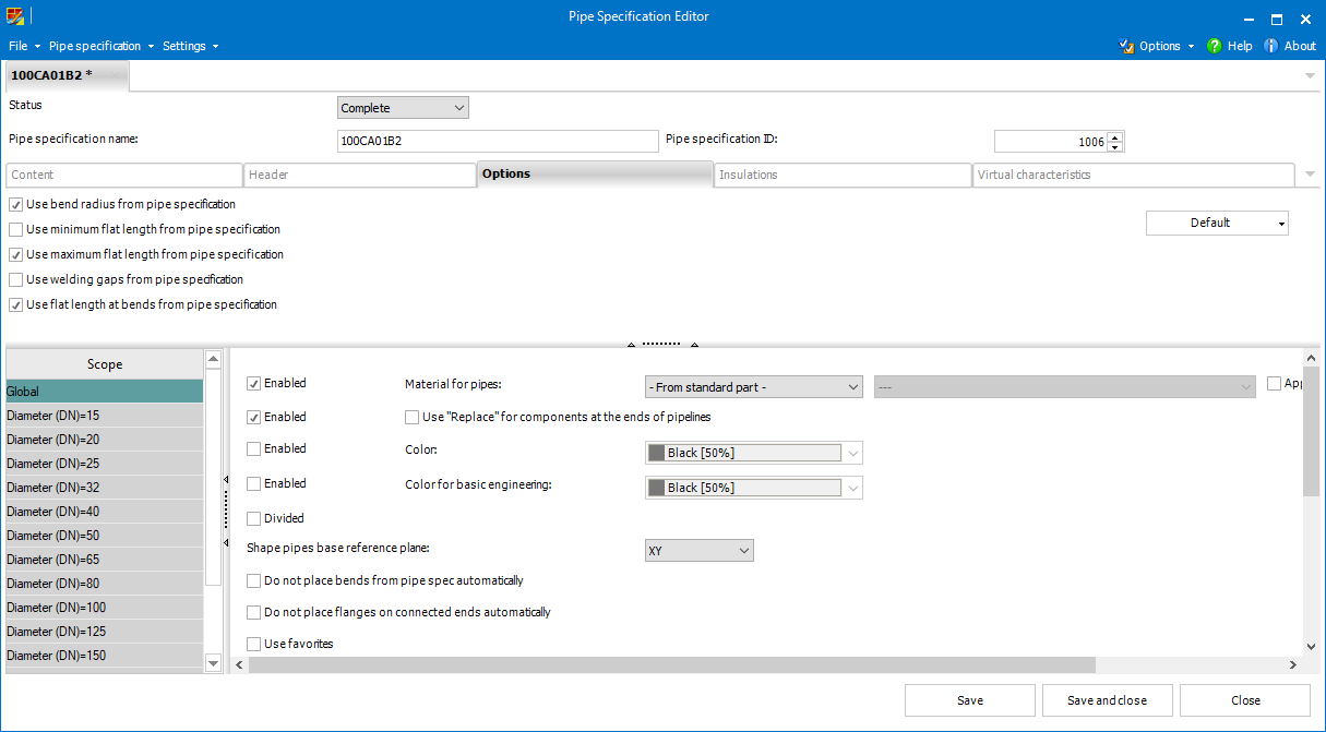
In the bottom-right section, the following settings can be set for individual scope items.
This option allows to set a material for the pipes of the pipelines generated using the current pipe specification.
If the option is enabled, it overrides the Apply material to pipes setting from the Plant Design Administrator.
 Applying material slows
down the process of generating pipelines significantly!
Applying material slows
down the process of generating pipelines significantly!
When this option is active, any component located at the end of an unconnected pipeline will behave as a manually placed fitting and will be replaced instead of deletion while performing Edit pipeline.
The setting is only available for the Global Scope.
If the option is enabled and a color selected, all the pipelines generated using the current pipe specification will get the defined color.
The setting is only available for the
Global Scope.
If the option is enabled and a color selected, the basic engineering pipes using the current pipe specification will get the defined color.
The
setting is only available for the Global Scope.
This checkbox provides default value for Divided which is available in the Generate pipeline and Edit pipeline dialogs of Smap3D Piping.
If the option is turned on, the generated pipes are divided into straight and bent sections.
The setting
is only available for the Global Scope.
The base reference plane (XY, XZ or YZ) for creating pipelines made of shape pipes and fittings.
The selected plane should represent a ground or floor plane of the piping assembly.
Creating pipelines with shape components requires that a connection of
each two line segments builds up a virtual plane which is parallel to
one of the base planes XY, XZ,
YZ.
The setting has an effect only in case the pipe specification contains
some shape pipes and fittings.
The setting is only available for the Global Scope.
This option should be activated in case the user wants to generate pipelines without placing standard bend/elbow fittings defined in the current pipe specification.
Bent pipes are placed instead in such a case.
If a pipeline path end is connected to some 3D geometry, Piping places a flange (if available for the respective pipe specification and parameters) on that end while generating a pipeline.
When this option is set, flanges are not placed on the connected ends.
When this option is checked, user can choose a flange which will be
placed to a connected end.
User can choose between regular flange
and counterflange.
The setting
has an effect only if the pipe specification contains flange and counterflange
in the same DN.
Gasket
is always placed automatically on connected ends, but only if it is defined
in selected pipe class. In very specific use cases, this general behavior
can be influenced with manual placing of specific Dummy-Parts.
When the option is set, rotation of concentric reducers placed using one of the place concentric reducer commands is locked.
When the option is active, pipes are cut off every maximum flat length and a Cutoff or Union fitting is placed automatically.
Represents the radius of a bend on a generated pipe.
This setting
overrides the bend radius value set in Plant
Design Administrator.
Pipes are generated only on segments which are equal or longer than the minimum flat length.
If the
minimum flat length is smaller than Min.
length tolerance, the pipe will not be generated and the error message
will not appear.
This setting
overrides the minimum flat length value set in Plant Design Administrator.
The length of the longest straight segment on which a single pipe can be generated (if the segment is longer, two or more divided pipes are placed).
This setting
overrides the maximum flat length value set in Plant Design Administrator.
If the option is enabled and a value set, a corresponding gap is added between generated pipes and also between generated pipes and fittings.
The gaps simulate the situation of the pipelines before welding.
This setting handles a gap between two coordinate systems and placing fittings using the Piping functions depending on a CS tolerance.
If the gap is smaller than CS tolerance setting, both coordinate systems are occupied for Piping.
So, Recalculate Pipeline will not place anything between the fittings.
Example:
Let us have two flanges
and a gasket between
them. The gasket is 2 millimeters wide.
If we delete the gasket and set the CS tolerance to 2.5 mm, the gap will be smaller than the tolerance.
The gasket won't be placed when performing Recalculate Pipeline.
This parameter is used for the pipelines generated with Divided checked (see above).
The value defines the length of a cylindric volume which is added to
both sides of each bent pipe part  .
.
This setting
overrides the flat length at bends value set in Plant Design Administrator.
Minimal cutting length is used to ensure manufacturability of bent pipes.
Bent pipes are extended by this value in both directions when a pipeline is generated with the Divided option.
When the actual length of a bent pipe is smaller than the allowed length defined by bend radius and minimum cutting length, the message box appears and the pipe is not be generated.
In case of bend 180°, it is necessary to use minimum technical tolerance 0.01 mm.
So, the length of the segment must be 2x bend radius + 0.01 mm.
This setting
overrides the Flat length at bends value. It does not have any effect
on elbow fittings.
Minimal clamping length is used to ensure manufacturability of bent pipes on a bending machine.
This setting is active only on segments between two bent pipes.
Value
of the minimum clamping length is used to calculate a cost saving length
of a bent pipe.
Additional Pipe Length sets the custom property Length according to the entered value.
If the option is enabled and a value is set, the custom property Length
of a pipe will be extended/shortened for any tube side/end that is connected
to coordinate system with an ET defined in PlantDesignGlobalOptions.xml
(including ET -1 Free End) .
The Additional Pipe Length property calculation with positive or negative value relates on the fitting/end treatment situation on each end of a pipe.
The value of the custom property doesn't fit to physical pipe length in CAD, maximum length is not affected.
It is
possible to input positive or negative value for the additional pipe length.
The
value of the custom property does not affect physical pipe length in CAD.