![]()
![]()
![]()
Working with shape components demands some special requirements in addition to those necessary for conventional piping components.
Shape components also require coordinate systems and axes (see the Coordinate Systems topic to get detailed information about the coordinate systems name convention).
These coordinate systems are necessary for connecting the components with shape pipes or other shape components.
 The x axis of each
coordinate system must always point in the direction of the input or output.
The x axis of each
coordinate system must always point in the direction of the input or output.
The coordinate system OUTPUT_POINT_1 serves as a component's reference point which determines its orientation.
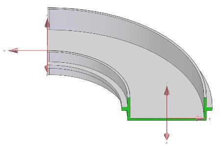
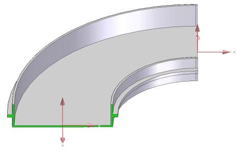
You can see examples of the left and right cable tray bends in the pictures below.
The displayed coordinate system in the front (in both cases) is OUTPUT_POINT_1.
The
axes (OUTPUT_AXIS)
on each end is not
shown in the picture below, but required.
For the correct function in Smap3D Piping each shape component (must be registered in the database as a standard part) must contain a characteristic for Orientation (e.g. Orientation or some equivalent characteristic defined for Shape components orientation in the characteristics file - see Piping Common for details).
 For proper function of Smap3D Piping with the component,
the orientation characteristic (its unit class) must be dimensionless.
For proper function of Smap3D Piping with the component,
the orientation characteristic (its unit class) must be dimensionless.
It must have one of the numeric values listed column Orientation in the table below.
Type |
Orientation |
Example of usage |
Note |
Universal |
0 |
square Air duct part |
The same geometry for all orientations |
Left |
1 |
Cable tray bend |
Geometry for left and right direction differs |
Right |
2 |
Cable tray bend |
Geometry for left and right direction differs |
Up |
3 |
Cable tray bend |
Geometry for up and down direction differs |
Down |
4 |
Cable tray bend |
Geometry for up and down direction differs |
Left/Right |
5 |
rectangular Air duct bend |
The same geometry for left and right direction |
Up/Down |
6 |
rectangular Air duct bend |
The same geometry for up and down direction |
When a shape
pipeline is generated, the component's orientation is related to the Shape
pipes base reference plane set within the relevant pipe specification.
If the shape components are designed to have gaskets placed in between them and shape pipes, the OUTPUT_POINT coordinate systems must have set a special End Treatment (ET=1004) for automatic placing of shape gaskets within CSInfo.
To get proper results, the coordinate systems must be offset outside the shape components (and pipes) by half the thickness of the gasket.