![]()
![]()
![]()
The Options  of Smap3D Piping provides
the user with settings which can be easily made directly in the Smap3D
Piping application.
of Smap3D Piping provides
the user with settings which can be easily made directly in the Smap3D
Piping application.
These settings apply only for the current user.
If you want to apply the settings from Plant Design Administrator, check Use default settings from Plant Design Administrator.
 The User
settings group is available even when this box is checked.
The User
settings group is available even when this box is checked.
Use subfolder for the settings below - specifies eventual subfolders for the below specified folders (for generated pipes and copied standard parts).
Folder for generated pipes - defines a folder where generated pipes and insulations are saved.
Copy parts to working folder - if checked, parts used on generated pipelines are copied to the folder specified by one of the sub-options.
Copy parts indexed - filenames of the generated parts within the working folder are indexed.
However, all the parts placed using the same QP method within the same generating run get the same index (filename).
Access
to these settings can be denied by the administrator in Plant Design Administrator
(Piping
Paths section).
Min. length tolerance - if a value is set here, the segments shorter than this value are suppressed (therefore pipes are not generated over them).
Create an axial relationship on flanges and gaskets - affects the creation of axial relationships for automatically placed flanges and gaskets.
 Axial relationships can potentially
cause the assembly to be over defined, or other mates to be disrupted.
Axial relationships can potentially
cause the assembly to be over defined, or other mates to be disrupted.
Different icons for automatically and manually placed fittings - if set, automatically and manually placed components are displayed with different icons in the Piping tree view.
Different icons for invisible parts - if set, visible and invisible components are displayed with different icons in the Piping tree view.
Highlight occurrences in CAD - when the setting is active, an occurrence in CAD is highlighted when the cursor is over the respective occurrence in the Piping tree view.
Switch to detail engineering after finish route
If the option is checked the detailed engineering will be automatically generated after closing a 3D sketch with a new pipeline path. Detailed engineering means that the pipeline will be generated with a desired pipe specification.
Show pipe preview
If checked, a preview pipe will be shown during drawing a new pipeline path in the 3D sketch.
Automatic synchronization - if checked, Piping makes a preventive refresh before actions such as Generate, Edit pipeline or Update all links.
If it is unchecked, it may increase performance but it is necessary to use Refresh, Refresh all or Refresh view after manual changes made (without Piping) in the piping assembly.
Do not display minimum flat length alert - suppresses the message which appears during the generating process in case pipe segments are shorter than the minimum flat length (set in the Piping Common section of Plant Design Administrator).
Create mates between shape pipes - when generating pipelines made of shape pipes, this option determines whether mates should be created between individual shape pipes or not.
Only for use with non-round cross-sections!
Group piping components in CAD assembly tree - when the option is set, all the components created and placed by Piping go into the Smap3D Piping folder in the assembly feature tree.
Use already opened document path for place - when placing a component (by the generating process) which is already placed within the piping assembly, but it has different file path, its copy is placed instead of placing the file from different location.
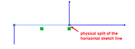
Automatic split line with a branch line - Splits lines with a branch line for an easier work with Remove/Adapt Pipe. When activated, get to the 3D sketch environment by creating a new 3D sketch with Create Route, Edit Route starts the 3D sketch environment for an existing 3D sketch to edit it, when closing/exiting the 3D sketch environment, all lines in the active 3D sketch feature are checked to ensure they are only connected at line end points.
If this is not the case and there are line elements connected along a continuous line (connection endpoint to line), the baseline is automatically split at this point (as with split line),
and then only endpoint to endpoint connections are made between the individual physical lines.
This automation works in SOLIDWORKS only with the above-mentioned functions of Smap3D Piping.
If the 3D sketch environment
is activated with native SOLIDWORKS functions, this automation is
NOT executed!
Collapse feature manager automatically - disables collapsing of the SOLIDWORKS FeatureManager structure tree after piping automations to enhance performance.
This option is checked by default.
If this option is deactivated, Piping will no longer collapse the SOLIDWORKS FeatureManager structure tree and the tree needs to be collapsed by using the native SOLIDWORKS functions.
Document name formula - sets a formula for display names of component occurrences within the Piping tree view. The display names can consist of values of selected properties and fixed characters.