![]()
![]()
![]()
In contrast to the pipes, the generating process of a shape pipe uses the 3D geometry of the part assigned in the Pipe Specification Editor.
Shape Pipes must be registered in the database as standard parts and must contain a variable characteristic (e.g. Length or some equivalent characteristic defined for Shape Pipe length in the characteristics file - see Piping Common for details).
The variable characteristic should control the length of the shape pipe through the equation that is used within the 3D model of the shape pipe to define its length.
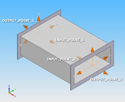
The 3D geometry of shape pipes must contain one pair of coordinate systems (INPUT_POINT and OUTPUT_POINT) and one axis (OUTPUT_AXIS) on each end (see the Coordinate Systems topic to get detailed information about the coordinate systems name convention).
 The x-axis
of each coordinate system must always point in the direction of the input
or output.
The x-axis
of each coordinate system must always point in the direction of the input
or output.
Connections between shape pipes and shape components are created just through the coordinate systems.
A generated shape pipe starts with one of its coordinate system pairs in the point where the component ends.
It is also recognized by the inherent coordinate system pair. Coordinate systems orientation also determines the spatial orientation of the generated shape pipe. Shape pipes and shape components are connected so that the INPUT_POINT of the shape pipe overlaps OUTPUT_POINT of the shape component, and vice versa.
If the shape pipes (and components) are designed to have gaskets placed between them, the OUTPUT_POINT coordinate systems must have set a special End Treatment (ET=1004) for automatic placing of shape gaskets within CSInfo.
To get proper results, the coordinate systems must be offset outside the shape pipe by half the thickness of the gasket.
In the picture below you can see an example of shape pipe geometry including the required coordinate systems.
The
axes (OUTPUT_AXIS)
on each end is not
shown in the picture below, but required.