![]()
![]()
![]()
With hydraulic components come various key names such as Threaded Joint Nipple, Threaded Joint Socket Unit and their reduced variants together with sub key names Component 1, Component 2 and Nut, designed to allow automatic placing of hydraulic components.
The components are placed as a whole unit with multiple components listed in the piping tree view.
Because it is typical for hydraulic components that each connection to a component can have a different type and a different application.
Typical on such components are spigot ends and socket ends.
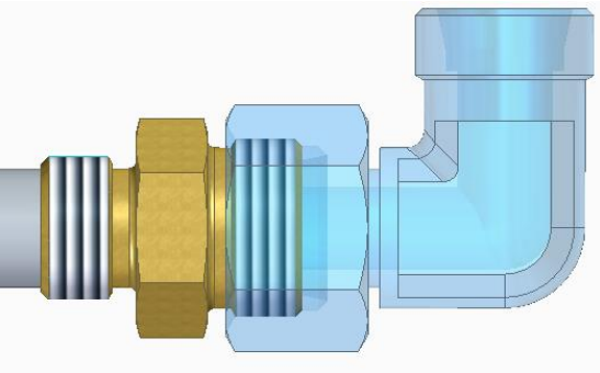
A Threaded Joint Nipple component must have INPUT_POINT and OUTPUT_POINT coordinate system and corresponding OUTPUT_AXIS with ET=15 (Cone Socket) End Treatment, therefore it is placed on a component/fitting with OUTPUT_POINT coordinate system with ET=16 (Cone Spigot).
Example:
The defined screwed fitting nipple (brass) with its cone socket connection point (ET=15), is automatically placed at the cone spigot end (ET=16) of the bend (blue transparent).
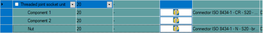
As Threaded Joint Socket unit there can be up to 3 different components defined.
It is always placed on a component/fitting with OUTPUT_POINT coordinate system with ET=15 (Cone Socket ends).
For Threaded Joint Socket unit in Pipe Spec Editor the multiple row key name Threaded Joint Socket Unit must be used.
The key name then allows to define sub rows with sub key names (Component 1, Component 2 and Nut).
Component 1
Component 1 must at least contain 2 coordinate systems.
Coordinate_system_1 mandatory with ET=16 (Cone Spigot) definition, that is placed to the coordinate system with ET=15 of the basic component.
Coordinate_system_2 mandatory with ET=0 definition (except Smap3D Plant Design library parts, there it is ET=9), where a defined Component 2 is placed too.
Coordinate_system_3 is optional with ET=8 definition, where a defined Nut is placed.
Component 2
Component 2 is optional, it must contain 2 coordinate systems.
Coordinate_system_1 with ET=0 (undefined), where this Component 2 is placed to Component 1 with coordinate system 2 (ET=9).
Coordinate_system_2 with ET=0.
Nut
Nut is optional, it must contain one normal coordinate system 1 and one Tapping point coordinate system.
Coordinate_system_1 with ET=8, where this Nut component should be placed to Component 1 coordinate system 3 (ET=8).
Tapping_Point_1 is required for Isometric.
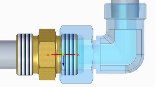
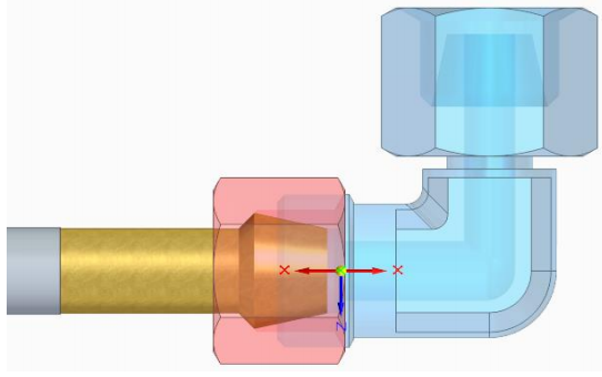
Example:
The defined welding nipple (brass) with its cone spigot connection point (ET=16) plus nut (red transparent) is automatically placed at the cone socket end (ET=15) of the bend (blue transparent).
For reducing there is a separate key name in Pipe Spec called Red. Threaded Joint Nipple, which has listed same key names as Threaded Joint Nipple.
For OUTPUT_POINT coordinate system with ET=16 usually a reduced socket component with ET=16 is used.
Example:
The defined reduced nipple (brass) with its cone socket connection point (ET=15), is automatically placed at the cone spigot end (ET=16) of the bend (blue transparent) when using Piping function Split route.
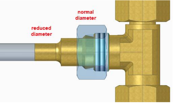
For reducing there is a separate key name in Pipe Spec called Red. Threaded Joint Socket Unit, which has listed same key names as Threaded Joint Socket Unit.
For OUTPUT_POINT coordinate system with ET=15 the nipple (Component 1) does have a reduced end, but all defined parts should be placed together.
Example:
The defined reduced welding nipple (brass) with its cone spigot connection point (ET=16) plus nut (red transparent) is automatically placed at the cone socket end (ET=15) of the tee (blue transparent) in a reduced tee situation.