![]()
![]()
![]()
Contents: Hide
This section serves to assign particular components (standard parts) to required combinations of key name, selected size parameter, and optionally other parameters available within the selected pipe specification. Each row within the table stands for one component.
The meaning of individual columns is described below.
Rows can be easily managed using the following context menu commands:
Add new row - Adds an empty row.
Remove - Removes the selected rows.
Copy rows - Copies the selected rows to the clipboard. The rows can be later pasted to another pipe specification, or application (typically, a spreadsheet).
Paste rows - Pastes rows from the clipboard to the active (opened and selected) pipe specification. The pasted rows must originate from a pipe specification with the exactly same number of non-size parameters.
Duplicate row - Makes a copy of the selected row(s) within the current pipe specification.
Edit - Launches the Pipe Specification Row Detail Editor. It allows to edit individual component parameters, and also offers some extra options which are not available within the user interface of the Content section.
Add additional component - Adds a sub-row for the selected row. This command is only available for shape pipes (or generally, the components of key names which have assigned the Shape pipe QuickPlace method). It allows the user to define fixed length shape pipe(s) and one variable length shape pipe. When a pipeline is generated using respective pipe spec, the pipes are composed primarily of the fixed length pipes. The remaining sections are filled with the variable length pipe.
 Rows which
have defined additional
items or virtual
characteristics (editable in the Row
Detail Editor only) are marked by the
Rows which
have defined additional
items or virtual
characteristics (editable in the Row
Detail Editor only) are marked by the  icon.
icon.
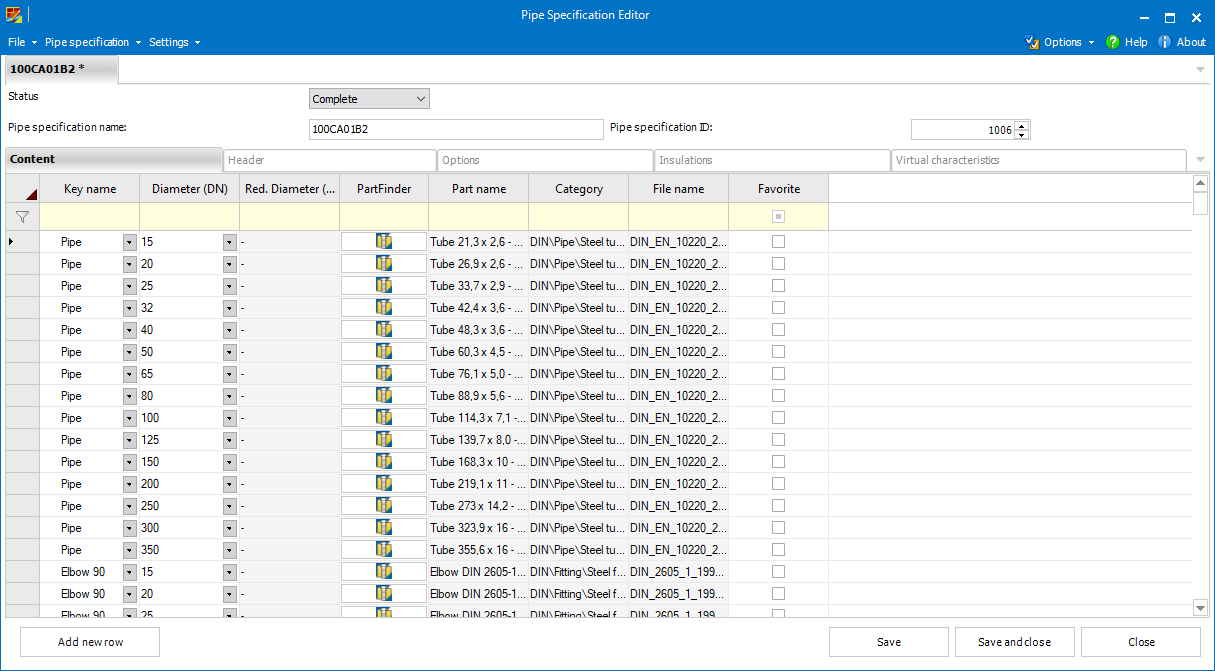
Available key names defined in the common settings can be selected from the drop-down.
The values for the size parameter (diameter typically) of the pipe specification can be selected from the drop-down. See Common settings for details.
The values for the non-size parameters (see Common settings for details) can be selected from the drop-down.
The presence
and order of individual parameters within the pipe specification can be
modified via the Pipe Specification columns dialog (Choose columns
in the Pipe specification menu). Remap
columns changes the meaning of the entered values
(it changes column while preserving values).
This parameter can only be set for the key names which have set the Reduction attribute in the common settings. If available the values can be selected from the drop-down.
The list
of values is the same as defined for the size parameter.
The particular standard parts can be selected via the respective standard parts provider which can be launched by selecting the corresponding button.
In addition to the main standard parts provider there can be also additional providers available.
The background
color of each component row corresponds to the standard parts provider
that provides the respective standard parts. For the main standard parts
provider the background is white, for additional providers it is the color
set in the Plant
Design Administrator.
The information about the standard parts (Part name, Category and Filename, typically) is displayed in separate columns. The values in those columns cannot be edited manually.
For the
standard parts selected by means of File System Provider, the Part Name
column displays Title of the selected file, while in the Category column
there is sub-folder structure of the File System Provider's standard
parts folder where the file is stored.
When using the File
system provider  , there are two possible ways
to select a part. It is possible to select an existing plant design component
(from the File System Provider's standard parts folder) or to create a
new plant design component using the Component
Wizard.
, there are two possible ways
to select a part. It is possible to select an existing plant design component
(from the File System Provider's standard parts folder) or to create a
new plant design component using the Component
Wizard.
File system provider does not support .
Some standard
part providers allow you to select not generated parts. Such parts can
be generated automatically on demand; i.e. when these are being inserted
for the 1st time to a pipeline by Smap3D
Piping. However, it is also possible to use Generate parts
from the Pipe Specification menu that generates all the not generated
parts within the active pipe specification. Please note that generating
greater number of parts may be time-consuming.
This column is useful when there are several components with the same key name (or from the same non-unique group) and size parameter (or other mandatory parameters, eventually) within one pipe specification.
In such case one of these non-unique components must be set as favorite to be pre-selected for the functions such as Generate pipeline or Edit pipeline.
The Overlay column is only available when the Insulations functionality is enabled for the pipe specification.
By checking the boxes, the user selects the components which should be overlaid with an insulation when it is generated.
The values set in this column serves for the automatic fitting placement from To-Do List (see the Placing Fittings to CAD topic for details).
If a P&ID ID value is identical with Article No' of some symbol in P&ID, such a fitting can be placed automatically by Place Fitting to CAD.
To enter the proper value, P&ID Component Database can be launched
by selecting P&ID  , and the required component should
be selected there. The respective value is then passed to the P&ID
ID column.
, and the required component should
be selected there. The respective value is then passed to the P&ID
ID column.
 For each size
parameter (and other parameter combinations eventually) within a pipe
specification the P&ID ID values must be unique for proper function.
That means there should not be two (or more) fittings with the same P&ID
ID and size parameter (diameter) value.
For each size
parameter (and other parameter combinations eventually) within a pipe
specification the P&ID ID values must be unique for proper function.
That means there should not be two (or more) fittings with the same P&ID
ID and size parameter (diameter) value.
P&ID ID values set in pipe specification can also
be utilized in Smap3D P&ID. Place
from specifications allows to select pipe specification
name and size and then displays filtered view of Component Database containing
only components with the same Article Numbers as the P&ID ID values
in appropriate pipe specification and size.