![]()
![]()
![]()
Contents: Hide
The Pipe Specification Editor's common settings define parameters and key names available for newly created pipe specifications.
It is equally important that these settings also define the way Smap3D Piping uses the components from the pipe specifications (e.g. when generating a pipeline).
Since such behavior is not defined within pipe specifications themselves, the common settings defines the way the pipe specification is represented.
 The Pipe
Specification Editor settings are stored in the PipeSpecificationCommon.pssx
file stored within the Smap3D Plant Design system configuration
folder.
The Pipe
Specification Editor settings are stored in the PipeSpecificationCommon.pssx
file stored within the Smap3D Plant Design system configuration
folder.
To select desired components within a pipe specification (e.g. when generating a pipeline) some selection criteria must be defined.
To be more specific, there must be exactly one size parameter defined within each pipe specification. The size parameter settings also defines the main unit for the pipe specification.
Additionally, each pipe specification can also have further non-size, mandatory or optional, parameters.
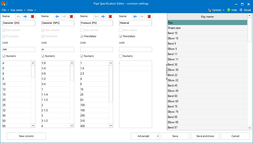
Each of the selection parameters is represented within the user interface of Pipe Specification Common settings as a column.
The order of the columns (and order of the pipe specification parameters)
can be modified by moving (left  or right
  ), existing columns
can be removed
), existing columns
can be removed  , new columns can
be added.
, new columns can
be added.
The selection parameters are defined using following options and settings.
Name of the selection parameter.
Individual
names can be set for various languages in advanced mode of common settings.
This setting determines whether the parameter defines some size (diameter typically) or not.
Each pipe
specification must contain just one size parameter (even though it is
possible to define multiple size parameters in the Pipe Specification
Common settings).
It is possible to set optionally a unit for each parameter. Unit of the Size column determines whether the associated pipe specification uses imperial or metric units.
This option determines whether the parameter values are numeric or not. It has an influence on the values sorting.
The values for the parameters can be managed within the list. New values can be added by entering into the last row.
Using context menu commands, individual values can be removed , moved up  or down
  manually, or the entire
content can be sorted automatically.
manually, or the entire
content can be sorted automatically.
Generally, key name represents a way of Smap3D Piping automatic processing, i.e. when, where and how can be such a component placed. In pipe specifications themselves, there are particular components (standard parts) assigned to individual key names.
In basic mode it is just possible to edit,
add ![]() or remove individual key names.
or remove individual key names.
Switching to advanced mode allows to fully manage all the key name parameters (see below).
 Making changes in the
advanced mode can be only recommended for expert users!
Making changes in the
advanced mode can be only recommended for expert users!
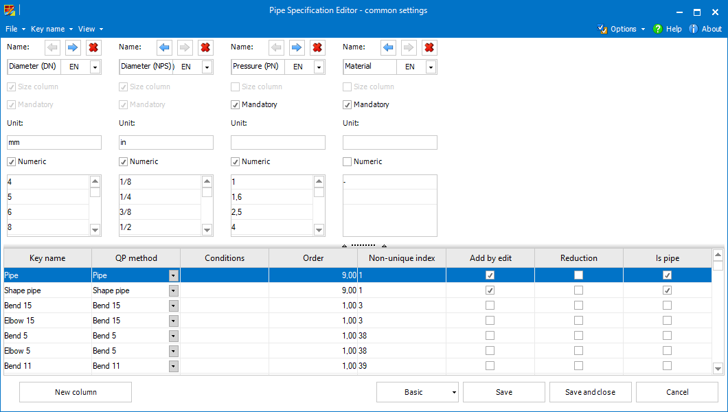
Key name identifiers (names).
Key names must be
unique. Any key name must be unique to any other key name in any language.
The translations of individual key names does not need to be unique.
So-called QuickPlace methods specify the way of placing components (where and how it should be placed).
Using this setting it can be determined when the components assigned to the given key name can be placed.
The components can only be placed when there is a component (in the relevant pipe specification) assigned to the key name which is the condition value.
Conditions can be set using the Key Name Editor.
If there
are multiple key names as a value, it is sufficient to fulfil one of the
conditions.
Conditions must be
set in accordance with specific QuickPlace method.
The values (these must be positive numbers) of this setting determines the order of placing components in process of generating pipelines.
The smaller the number is, the sooner such components are placed.
E.g. pipes
should be usually placed at the end of the generation process, gaskets
should be placed before placing flanges, etc.
When several key names are given the same value (Non-unique index), they form so-called non-unique groups.
These groups should associate the components (key names) which can be placed on the same place on a pipeline path (T-connection, specific angle, etc.).
This setting determines the behavior of the components with a given key name by the process of editing a pipeline (changing pipe specification or the parameters of a pipeline).
If the setting is checked, the components are placed to the edited pipeline automatically (if there is a corresponding place on the pipeline path) even if these were not part of the original pipeline (before editing).
The presence of the reduction attribute allows to set reduced diameter (as an extra parameter) for the components assigned with such key name.
Reduced
diameter should be available typically for components such as reduced
tees, collars, concentric fittings (reducers/expanders), etc.
Reduction
does not necessarily mean size reduction, components using more End Treatments
on their ends should be also given the reduction attribute.
This setting should be active for key names specifying pipes (or shape pipes), i.e. components which fills the space between fittings.
Such components should have typically the largest Order number.
This dialog allows the user to edit individual key names and their parameters.
Similarly to the main common settings form, Key name editor can be displayed in basic and advanced mode.
While the basic mode allows only to edit the respective key name's name in the current user interface language, using the advanced mode, it is possible to edit all the above mentioned parameters.
Clicking
the  /
/ button switches displaying of QuickPlace method names between localized
(more clear for the users) and internal values (more accurate for eventual
troubleshooting).
button switches displaying of QuickPlace method names between localized
(more clear for the users) and internal values (more accurate for eventual
troubleshooting).
Clicking
the +/- button in the Conditions field displays the full list of key names.
By checking, the respective key name is added as a condition value, while
unchecking removes it.
Key name
editor opened for the Union key name in advanced mode displays (and allows
to rename) also its sub-components.
As an extra feature, common settings allows the user to predefine a list of names for virtual characteristics that can be set as details for individual components.
Virtual characteristics for additional items in the File menu opens (and also creates, if it does not exist yet) the PipeSpecificationVirtualCharsCommonNames.txt file (stored within the Smap3D Plant Design system configuration folder).
Every single row of this file stands for a virtual characteristic name (empty rows are ignored).
The Additional Items Mappings form (can be opened from the File menu) allows the user to map the required properties of the standard parts assigned as additional items to additional component features ITEM_CODE and ITEM_DESCRIPTION.
For details, please refer to the Bolts, Washers, and Nuts (Isometric) section of help.
As the name suggests, the Pipe Specification Header defaults form serves to define default parameters (and their values) for pipe specification headers.
A header parameter can be added by selecting the New parameter.
For each parameter a section appears that allows the user to enter its Name and Values.
If set, the Mandatory flag forces any pipe specification creator to set a value for the respective parameter (the other parameters do not require any value to be set).
The order of the parameters can be adjusted using the up and down
buttons.
Any unnecessary parameter can be removed using the remove parameter.