![]()
![]()
![]()
Contents Hide
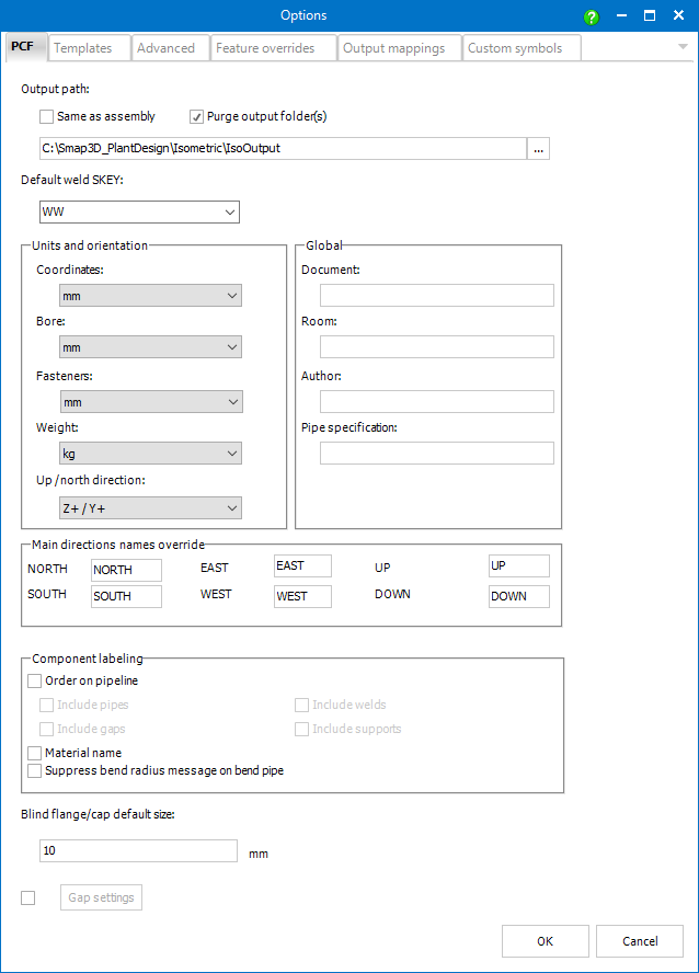
Output path is the location where the isometric drawings, messages, and reports should be generated.
It is possible to set a constant path or - by checking Same as assembly - to generate the drawings always to the current source data folder.
As default, the drawings are named from the corresponding pipeline path (or the 1st pipeline path in case there are several connected pipelines and the Attempt to generate single drawing option is active).
If Purge output folder(s) is active, all the existing DXF, PCF, IDF, MES, MTC and LIS files are deleted from the output path (including the drawing style sub-folder if set) before generating drawings.
Sets the SKEY
value which is assigned automatically to gaps recognized as welds.
![]()
Default weld SKEY and ISO_WELD_SKEY apply only to welds detected using welding gaps or to welds detected automatically between two components/pipes ends with explicitly defined (by direct edit or by ISO_CONNECTION custom property) welded (butt weld or socket weld) End Treatment.
![]() ISO_WELD_SKEY value set for a pipeline
path overrides the default weld SKEY value for all the welds on that pipeline path.
ISO_WELD_SKEY value set for a pipeline
path overrides the default weld SKEY value for all the welds on that pipeline path.
Coordinates - this setting is applied to coordinates, component
lengths, etc. Since the source data
already contains units, this setting determines the unit to which
all the dimensions will be recomputed in the resulting isometric drawings.
Bore - sets units for bore diameters. Since these dimensions
are taken from source data as dimensionless, for the proper result
the same units as used in source data should be used.
Fasteners - sets fasteners units. Since these dimensions are
taken from source data as dimensionless, for the proper result the
same units as used in source data should be used.
Weight - sets weight units. Since the weights are taken dimensionless
from source data, the same units as used in the source data should
be used for proper results.
Up / north direction - defines up direction within the source data and maps north direction (displayed in the isometric drawing). E.g. the value of Z+ / X- defines that the positive direction of the z-axis points up while the negative direction of the x-axis points north.
The values entered in the Document, Room, Author and Pipe specification fields can be handed over to the isometric drawing header.
![]() The values will be available
in the resulting drawing only in case the drawing template contains corresponding
items.
The values will be available
in the resulting drawing only in case the drawing template contains corresponding
items.
These settings manage the appearance of various labels in the resulting isometric drawings.
Order on pipeline determines whether labels (rounded rectangles) with ordinal numbers should be displayed.
If the box is checked ordinal numbers are generated for fittings automatically. Using the additional checkboxes it is possible to take into account also pipes, welds, gaps and supports.
![]() The order labels display values
of the Pipeline Order feature.
The order labels display values
of the Pipeline Order feature.
![]() Ordinal numbers are not assigned
to special components such as split point, location point, flow arrow,
bolts, nozzles, messages, etc.
Ordinal numbers are not assigned
to special components such as split point, location point, flow arrow,
bolts, nozzles, messages, etc.
When Material name is checked, drawings will also contain labels with part identifiers (part name typically) taken from ITEM_CODE (PCF feature).
![]() ITEM_CODE is mapped to the Title
file property by default. Mappings can be set/modified in Output
mappings section of the Smap3D Isometric
options.
ITEM_CODE is mapped to the Title
file property by default. Mappings can be set/modified in Output
mappings section of the Smap3D Isometric
options.
Suppress bend radius message on bend pipe disables the transfer of this information to the PCF file / Isometric drawing.
This setting is intended for finishing components (such as blind flanges or caps) which have only one pair of coordinate systems (INPUT_POINT, OUTPUT_POINT).
Since the Personal ISOGEN® requires two end points for such components, the second one is calculated using this setting.
![]() For the components containing
the TAPING_POINT
or TAPPING_POINT coordinate system this value is not taken into account.
For the components containing
the TAPING_POINT
or TAPPING_POINT coordinate system this value is not taken into account.
Using these settings it is possible to set the way Smap3D Isometric manages gaps in the source data.
When the checkbox is not checked the gaps
are managed as follows:
if a gap is smaller than or equal to tolerance
it is ignored
if a gap is matching (± tolerance) the welding gap width defined
in the pipe
specification, a weld component is added
otherwise a gap component is added.
With the checkbox checked, Gap settings is available. Using the Gap Settings Editor it is possible to adjust 4 ranges of gap length (+ one fixed).
For each range any of the following actions
can be set:
Ignore - the gap is ignored (filled with a not-on-material-list
pipe)
Insert weld - weld component ![]() is added
is added
Insert gap - gap component is added
Split drawing - split component ![]() is added,
i.e. the drawing will be split at this point.
is added,
i.e. the drawing will be split at this point.
The first range is automatically set from zero to the tolerance and the action is set to Ignore.
The upper limit of the previous rule is always tied to the lower limit of the following rules.
![]() For a gap matching (± tolerance) the welding gap width defined in the
pipe specification, a weld component is always added (independently on
the other settings).
For a gap matching (± tolerance) the welding gap width defined in the
pipe specification, a weld component is always added (independently on
the other settings).