![]()
![]()
![]()
Smap3D Piping allows the user to check the correctness of the designed pipelines from different perspectives.
 To get correct results,
design checks requires to have the checked pipelines composed of the components
containing proper CSInfo.
To get correct results,
design checks requires to have the checked pipelines composed of the components
containing proper CSInfo.
This check examines the pipelines in terms of CSInfo consistency within the pipeline components.
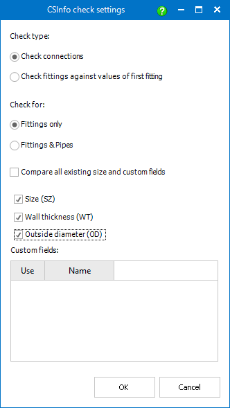
The CSInfo check can be specified using the following settings.
This setting determines the components whose parameters are compared.
When Checking connections is set, the check examines the pairs of coordinate systems which are connected together (adjoining components) and compares the specified CSInfo parameters (see below).
Such a check is suitable mainly for the pipelines containing sections of various diameters (e.g. a flowmeter connected using two reducers).
With Check fittings against values of first fitting selected, the check compares the selected CSInfo parameters (see below) of all components on the selected pipeline with the parameters of the first pipeline component (the top one below the pipeline node in the Piping tree view).
Such a check should be used especially to ensure the pipeline components have all the same size, etc.
This setting determines whether to check the consistency of the fittings only or to take the pipes into account as well.
When Fittings only is set, the check only compares CSInfo of fittings, pipes are ignored.
It could be useful in the cases when pipe information is not important or is not filled.
With Fittings & Pipes selected, the check compares CSInfo of all fittings and pipes.
In addition to the above mentioned settings, it is possible to specify the CSInfo parameters which should be compared.
Compare all existing size and custom fields sets all CSInfo parameters to be compared. As an alternative, it is possible to set the desired combination of size parameters - size (SZ), wall thickness (WT) and outer diameter (OD) - and eventual custom parameters.
 The SZ
parameter values are compared as strings (e.g. DN 50 and DN50 are not
the same values!), while the WT and OD is checked as a numeric value with
unit).
The SZ
parameter values are compared as strings (e.g. DN 50 and DN50 are not
the same values!), while the WT and OD is checked as a numeric value with
unit).
The parameter Outside Diameter (OD), available in the Coordinate System Wizard, is used for the extended evaluation of weld seam attributes in Isometric.
To ensure a uniform working method, this new parameter OD is also available in the Piping Design check CSInfo.
This design check examines the pipelines from the perspective of flow direction. That is why it can be only performed for the pipelines which have flow direction defined.
Technically, the sequence of OUTPUT_POINT coordinate systems and their Input/Output parameter (IO) of CSInfo for all pipes and fittings of the pipeline is checked.
The check is successful if the respective OUTPUT_POINT coordinate system (or more precisely, its x-axis) has the same direction as flow direction and IO=2 (output) or IO=0 (not specified), or if it has opposite direction to flow direction and IO=1 (input) or IO=0.
A flow direction can be set for a pipeline (path) by assigning
(via P&ID To-Do List) to a line in
P&ID, which have a flow direction set.
An alternative way is to use the Set
flow direction command.
To perform a design check, follow these steps:
 from the Smap3D Piping toolbar.