
![]()
Contents Hide
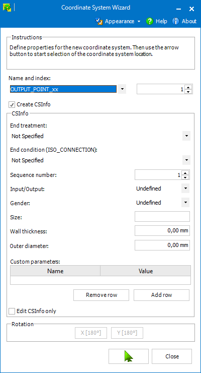
The goal of this topic is to describe in detail the individual controls of both application screens (steps).
The controls on the initial screen are always the same (with minor exceptions).
In the Name drop-down the desired coordinate system type should be selected.
The Index numeric up-down serves to set the coordinate system index.
 When the
value is set to zero, the coordinate
system is created without any index.
When the checkbox is checked, it is possible to specify CSInfo (within the CSInfo group below) for the created coordinate system.
 CSInfo
is only supported for certain coordinate system types.
This group of controls allows the user to specify values for individual CSInfo parameters.
Control |
CSInfo parameter |
End Treatment |
ET |
End Condition (ISO_CONNECTION) |
EC |
Sequence Number |
SN |
Input/Output |
IO |
Gender |
GR |
Size |
SZ |
Wall Thickness |
WT |
Outer Diameter |
OD |
Custom parameters |
C_xx |
When this setting is on, the function of Coordinate System Wizard is switched from creating coordinates system to editing (or defining) CSInfo of an existing coordinate system.
No new coordinate systems will be created.
The rotation buttons allow the user to set the desired spatial orientation for the just created coordinate system.

When creating new coordinate system, the second screen lists the geometry features which can be selected within the active SOLIDWORKS document to define the new coordinate system position.
In case of editing CSInfo (Edit CSInfo only is set), the user can select the desired coordinate system within the active document, or (if the active document is an assembly) select a component which contains the desired coordinate system.
If this is the case, a list of the coordinate systems included in the selected part is displayed and the user can select the one (and confirm by double-click or select Use selected).