![]()
![]()
![]()
Contents Hide
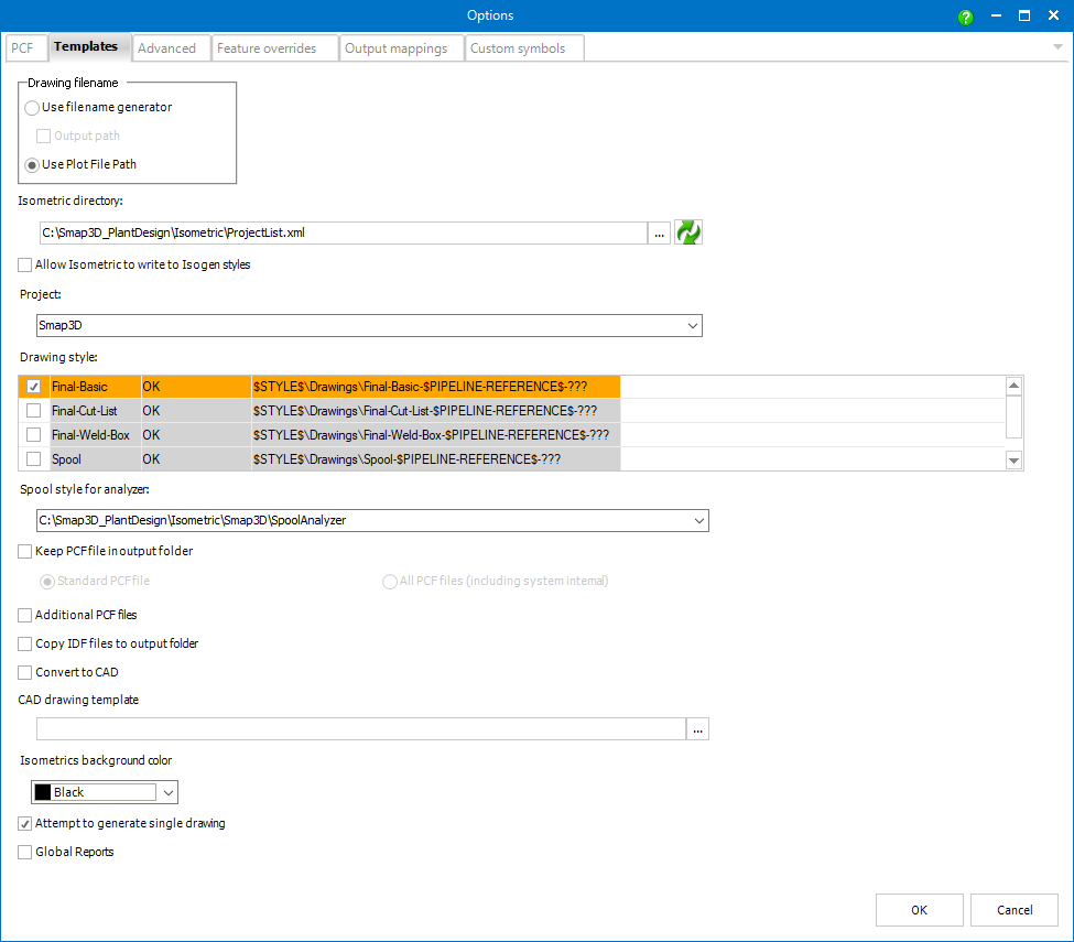
This option uses settings from Plant Design Administrator.
Use Plot File Path allows users to use Isogen© dynamic file naming.
Dynamic file naming is a method of naming files output by Isogen© using dynamic attribute values. This applies to all output files, such as the drawings and reports. Both drawings and reports file names can be set in I-Configure, but additionally Plot File Path (which defines both folder and file name) for drawings can be set in Isometric. This method can also be used to create folders.
It is the location where isometrics projects should be stored to be applicable as templates for creating isometric drawings.
To select such a directory properly the ProjectList.xml file (stored inside) should be selected (via browse dialog).
Particular Project and Drawing styles can be then selected below.
Allows to change/adapt existing dynamic file naming definitions settings
that are in both Isometric and I-Configure, such as units and drawing
file name. Checking causes a new button ![]() next to
each existing drawing style to appear.
next to
each existing drawing style to appear.
![]() Opens an Isometric
Output File Name Editor dialog with the corresponding path.
Opens an Isometric
Output File Name Editor dialog with the corresponding path.
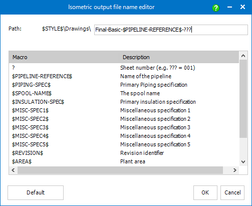
Isometric Output File Name Editor contains all available macros (variables). Macros define a syntax for drawing file names based on the new Isogen© Dynamic File Naming method.
Each macro can be combined individually or together with others to a desired file name syntax. It is possible to use strings and/or allowed characters.
Default changes the path to $STYLE$\Drawings\Name-of-style-$PIPELINE- REFERENCE$-??? so the user can get back to a working setup.
If the value of a style is Error then there is a mismatch in Isometric and an I-Configure settings of a style, select the word Error to learn more about the issue. To fix the error, just check Allow Isometric to Write to Isogen Styles, select the word Error and the I-Configure settings is changed automatically to match the Isometric settings or fix the mismatch manually in I-Configure.
If the value of a style is OK, then the settings in Isometric matches settings of the corresponding Isogen style, visible in I-Configure under Plot File Path property.
The definitions are then used for file names of the drawings that will be generated with this style in the future. It does not overwrite old drawings that were generated before this Plot File Path definition was made.
![]() File
names for reports can also be based on Isogen © Dynamic File Naming, this
can be set in the I-Configure tool for the respective style and its reports.
File
names for reports can also be based on Isogen © Dynamic File Naming, this
can be set in the I-Configure tool for the respective style and its reports.
![]() When
generating drawings from a 3d pipeline with more than one style at once,
where assembly name is used for drawing filename, there must be an additional
fixed differentiator in the plot file path definition for the styles.
Otherwise, only one drawing is generated in the output folder, which is
overwritten several times.
When
generating drawings from a 3d pipeline with more than one style at once,
where assembly name is used for drawing filename, there must be an additional
fixed differentiator in the plot file path definition for the styles.
Otherwise, only one drawing is generated in the output folder, which is
overwritten several times.
The Templates tab contains the Spool Style for Analyzer settings.
Spool Analyzer requires a specifically adapted ISOGEN© spool style.
 The spool style for the analyzer
CANNOT be the same as the spool style used for Isometric drawing creation.
The spool style for the analyzer
CANNOT be the same as the spool style used for Isometric drawing creation.
A prepared Spool Analyzer style from the default data is available. It is a copy of the spool style for Isometric drawing creation, which has been adapted to the Spool Analyzer requirements. These included ISOGEN© spool styles are ready to use.
It is also possible to adapt a custom spool drawing style for use with Spool Analyzer.
Creating the necessary separate Spool Analyzer style, from the existing style as a copy is highly recommended.
If all previous steps for the ISOGEN© style creation have been executed correctly, the created style for Spool Analyzer can be selected and set here.
Save the settings to use the Spool Analyzer in the Piping assemblies.
This box determines whether the PCF files (created by Smap3D Isometric as input for Personal ISOGEN©) should be deleted (default) or kept in the output path.
Standard PCF File is checked by default and works as Keep PCF File in Output Folder.
All PCF Files makes Isometric to copy also PCF files that are used internally to the defined output folder.
Additional PCF Files generates to the output path a PCF file per bent pipe.
Checking this box enables to copy IDF files (generated through the Personal ISOGEN© run) to the output path.
Checking this box allows, if a proper CAD drawing template is selected, to export automatically the resulting isometric drawings (created in DWG format) to the CAD native drawing format.
![]() To get correct results, the
units in the isometric drawings (DWG) and selected CAD drawing template
must match.
To get correct results, the
units in the isometric drawings (DWG) and selected CAD drawing template
must match.
Sets the background color of the isometric drawing previews displayed in Step 4.
If checked, Smap3D Isometric will try to create just one drawing containing all the pipelines.
It is only possible in the case that those pipelines (pipeline paths) are connected together and are not too complex.
If they are not, several drawings will be created.
This fact will be also mentioned in the output log (available in Step 4).
If the box is not checked a separate drawing will be created for every single pipeline.