![]()
![]()
![]()
Contents Hide
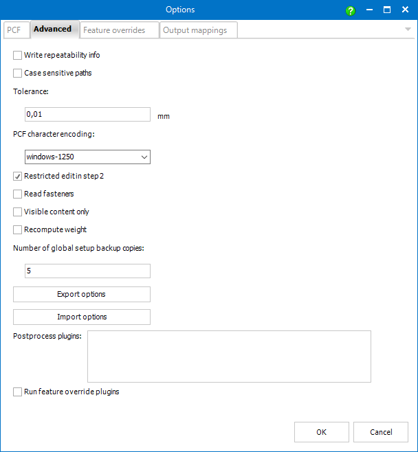
This option determines whether paths differing in letter case only are taken as different or the same.
This setting should mainly prevent various errors due to rounding.
If the distance between two points (coordinate systems of adjoining components typically) is smaller than the tolerance, the two points are taken as one (no gap is placed between them).
The tolerance value should be (much) smaller than common used welding gap widths.
This drop-down allows to adjust the character encoding of the PCF file to fit the currently used character set.
The default value is obtained from the current Windows settings.
When the box is checked (default) it is only possible to edit values of ComponentType, SKEY and user edited features in step 2.
Unchecking allows the user to edit any value.
Activating this option allows Smap3D PCFExport to analyze physical fasteners in source assemblies.
![]() The option is switched off by
default due to performance reasons.
The option is switched off by
default due to performance reasons.
If this option is set, weights of components within the source assembly (specified in step 1) are recomputed automatically according to their actual dimensions and densities.
![]() The option is switched off by
default due to performance reasons.
The option is switched off by
default due to performance reasons.
When global setup is modified from Feature Overrides or Output Mappings new file is created and the previous one is set as a backup copy.
Using this setting it is possible to set how many backup copies should be preserved.
These commands allow you to export the current local settings and save project-specific settings, that can be imported later (or by another user), or used in conjunction with /o command line parameter.
Post-process plugins can be programmed to automatically perform specific tasks with output files generated by ISOGEN after the generation of the isometric drawings, as well as any separate reports.
For example:
automatic transfer of report files in CSV format to a specific ERP system
automatic conversion of drawing files into specific file formats for long-term archiving
By default, there are no entries in the window. To get existing post-process plugins displayed in it and to be able to activate them, the corresponding plugin files (*.DLL) must be contained in the standard plugins directory of a Smap3D Plant Design installation.
Default path to the directory is: C:\Program Files\CAD-Partner\Smap3D Plant Design 20xx\Plugins.
A compiled plugin as example (Isometric.PostprocessShowFiles.dll) is provided. Read and follow the included Readme.txt to put this sample plugin into operation if needed.
Since the plugin interface can only work with plugins that meet our programming requirements, a Visual Studio C# project as a template and description for programmers is provided as well.
This should enable experienced programmers to quickly develop their own post-process plugins for this interface. Both are in the custom directory, default path is: C:\Program Files\CAD-Partner\Smap3D Plant Design xxxx\Custom.